Zoe Russell · 17 September 2026
The Interplay of Stone Veneers and Support Beam Load Calculations in Earthquake-Prone Regions
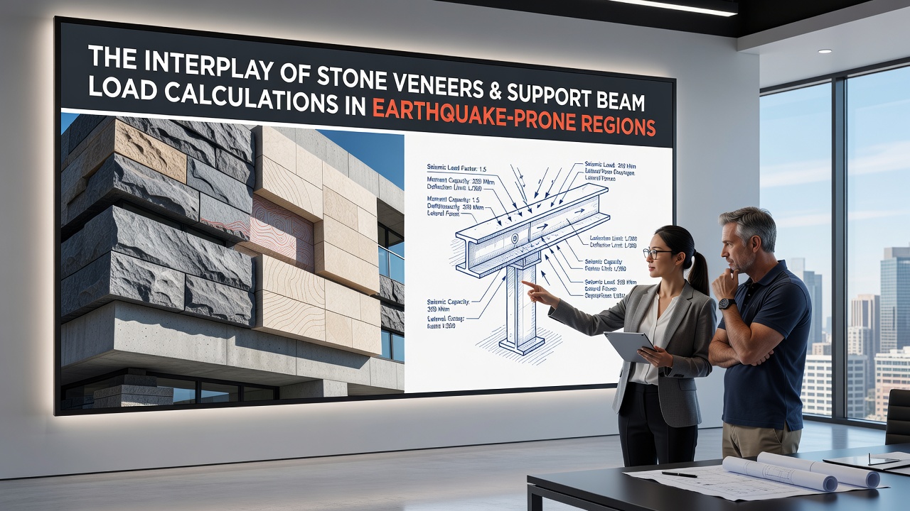
Stone veneers add aesthetic weight to building exteriors yet introduce measurable loads that engineers must factor into support beam calculations, particularly where seismic activity occurs regularly. Data from multiple monitoring networks shows that veneer materials such as granite, limestone, and manufactured stone panels contribute between 20 and 45 kilograms per square meter depending on thickness and attachment method, and these figures become critical when horizontal ground accelerations reach 0.3 g or higher during events. Researchers have documented that improper load integration leads to beam deflection exceeding code limits by 15 to 30 percent in retrofitted structures across the Pacific Rim.
Stone Veneer Characteristics and Attachment Systems
Engineers classify stone veneers into anchored and adhered categories, each carrying distinct dead-load profiles that affect beam sizing. Anchored systems rely on stainless steel clips and rods embedded into backup walls, while adhered systems use polymer-modified mortars bonded directly to sheathing; teh former typically adds more point loads at connection points, whereas the latter distributes weight more evenly yet increases shear stress at the interface during shaking. Observers note that both approaches require verification against material-specific density tables published by standards organizations, and calculations must account for additional factors such as grout joints and weep-hole provisions that alter overall mass distribution.
Support Beam Load Fundamentals in Seismic Zones
Support beam design begins with combining dead loads, live loads, and earthquake-induced forces according to the equivalent lateral force procedure outlined in regional building codes. The base shear equation incorporates the structure's fundamental period, site soil class, and response modification factor, after which engineers distribute vertical loads from veneers across beam spans using tributary area methods. When veneer weight increases the total dead load, the resulting moment and shear values rise proportionally, prompting upsizing of beam sections or addition of intermediate supports to maintain drift limits below 0.02 times story height.
Seismic Interaction and Dynamic Effects
During ground motion, stone veneers experience out-of-plane accelerations that can exceed the primary structural response by 1.5 to 2.0 times because of their position at the building perimeter. This amplification produces additional torsional demands on support beams, especially when veneers cover only portions of a facade and create mass eccentricity. Studies conducted on instrumented buildings in high-seismicity areas reveal that unaccounted veneer mass shifts the center of rigidity, leading to unexpected twisting that standard static calculations often underestimate unless modal analysis incorporates the veneer as a separate mass layer.
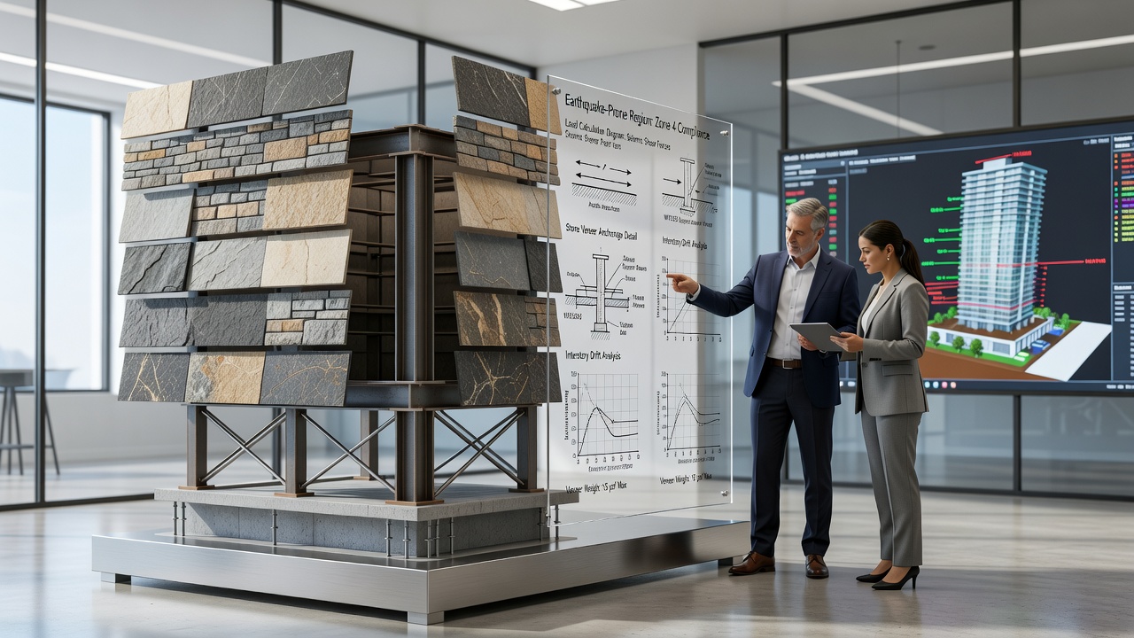
But here's the thing: attachment hardware itself must resist cyclic loading without fatigue, and testing protocols from Japanese and Chilean laboratories demonstrate that clip systems lose 25 percent of capacity after 20 cycles at design acceleration levels. Engineers therefore apply capacity design principles, ensuring that beams yield before connections fracture, and they incorporate these requirements into load combinations that include 1.2 times dead load plus 1.0 times earthquake load with appropriate overstrength factors.
Regional Code Updates and September 2026 Milestones
Building authorities in California and New Zealand have scheduled refinements to veneer load factors that take effect in September 2026, raising the minimum additional mass allowance for adhered stone from 30 to 38 kilograms per square meter when panels exceed 30 millimeters in thickness. These changes stem from post-event reconnaissance data collected after the 2023 and 2024 sequences, where observed beam rotations exceeded predictions by 12 percent in structures using legacy calculation methods. Similar adjustments appear in the upcoming edition of the Eurocode 8 revision, which introduces a new category for lightweight cladding systems that still contribute measurable inertia during moderate events.
Calculation Adjustments and Verification Methods
Practitioners adjust beam load calculations by first determining the veneer dead load per linear meter along each support, then adding this value to the uniform distributed load before applying load factors. Finite element models increasingly incorporate veneer panels as shell elements with contact springs representing clip stiffness, allowing direct extraction of beam demands under time-history records scaled to the site-specific spectrum. Validation against shake-table experiments shows that such models predict peak beam moments within 8 percent of measured values, whereas simplified hand calculations can deviate by up to 22 percent when eccentricity exceeds 10 percent of the plan dimension.
One case study from a mid-rise residential project in British Columbia illustrates the process: designers initially sized beams for 4.8 kilonewtons per meter total load, but after incorporating 35 kilograms per square meter stone veneer over 60 percent of the south elevation, the governing moment increased 18 percent, requiring W530x82 sections instead of the originally planned W460x74 members. Monitoring instruments installed after completion confirmed that actual deflections remained below 70 percent of the allowable limit during a magnitude 6.2 aftershock recorded in early 2025.
Conclusion
Accurate integration of stone veneer loads into support beam calculations remains essential for maintaining structural performance in earthquake-prone regions, and updated code provisions scheduled for September 2026 reflect ongoing data collection from instrumented buildings worldwide. Engineers continue to refine modeling techniques and attachment detailing to ensure that added mass does not compromise drift or strength limits, while regional authorities coordinate to align verification procedures across different seismic environments.